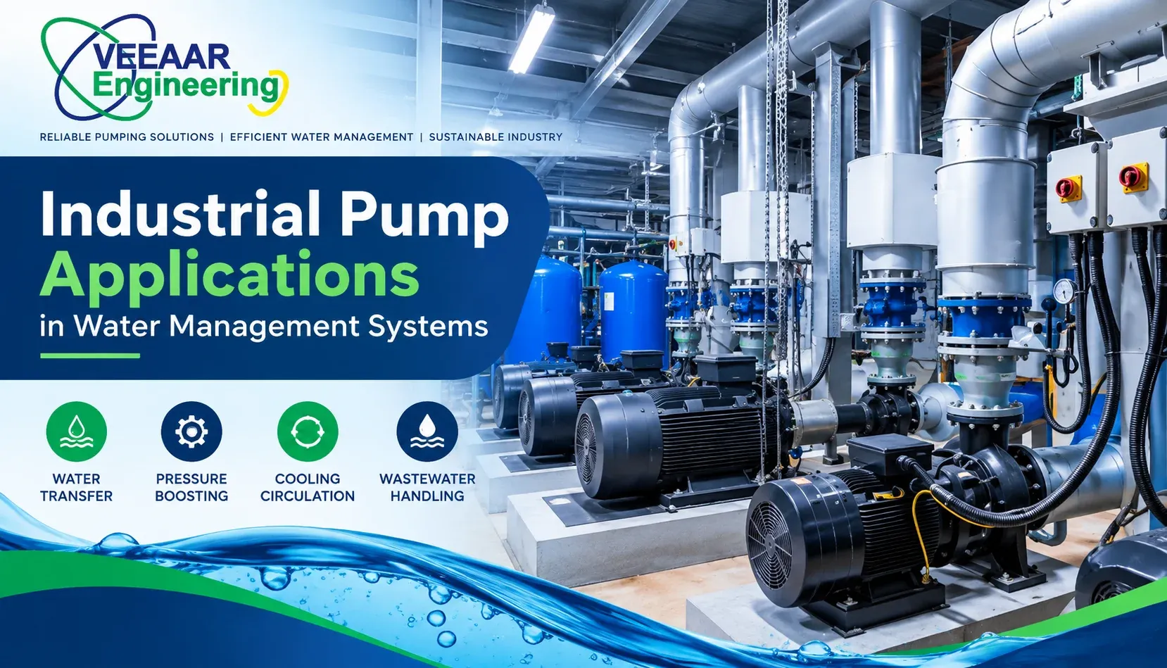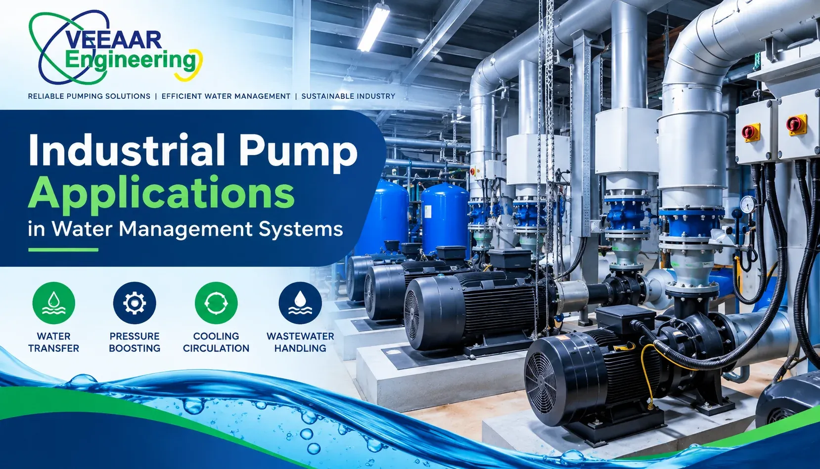
- Veeaar Engineering
- Oct 07, 2026
Industrial pumps move water through the complete operating chain: source intake, raw-water transfer, treatment, storage, pressure boosting, process circulation, cooling, drainage and wastewater handling. The correct pump is therefore selected around a duty point and system conditions—not simply around pipe size or motor power. Flow, total dynamic head, liquid quality, operating hours, suction conditions, control method and maintenance access all influence whether the installed system will be efficient and reliable.
Veeaar Engineering describes its industrial pump range for water, chemical, oil and other process-fluid duties. For water-management projects, buyers should request the exact proposed model, construction material, performance curve, efficiency, motor data, seal arrangement and permitted operating range. General catalogue descriptions help create a shortlist, but a project-specific datasheet and curve are needed before approval.
Where pumps fit in an industrial water system
| Water-management stage | Typical pump duty | Main selection concern |
|---|---|---|
| Source and intake | Lift raw water from borewell, sump, river or reservoir | Suction level, solids and seasonal variation |
| Transfer and storage | Move water between tanks or process areas | Flow target, static head and pipeline loss |
| Treatment | Feed filters, membranes and chemical processes | Stable pressure, material compatibility and control |
| Distribution | Maintain pressure at multiple demand points | Variable demand, minimum flow and redundancy |
| Cooling and circulation | Recirculate water through equipment or towers | Continuous duty, temperature and energy use |
| Drainage and wastewater | Remove storm water, effluent or sludge-bearing water | Solids passage, clogging risk and level control |
Raw-water intake and source transfer
Intake pumps may work with changing water levels, suspended matter and long suction or discharge routes. The design must establish the lowest expected source level, maximum delivery level and all pipe losses between them. A pump selected only for normal conditions can lose capacity when the source drops or the filters become dirty. Submersible arrangements avoid some suction-lift problems, while surface pumps require careful attention to available net positive suction head, priming and air leakage.
Screens, strainers and approach velocity affect the pump as much as the impeller. Debris accumulation can increase suction loss and trigger cavitation-like symptoms. The intake should allow inspection and cleaning without unsafe access. Where a production plant depends on a single source, duty-and-standby pumps, level alarms and an alternate supply path can be more valuable than choosing one oversized machine.
Transfer between tanks and process areas
A transfer pump usually moves a known volume within a defined time. Begin with the usable tank volume and required transfer window, then calculate the flow rate. Add static elevation difference and friction loss through straight pipe, bends, valves, strainers, meters and equipment. The resulting duty point should fall in a stable, efficient part of the proposed pump curve rather than at its extreme edge.
Tank levels change during transfer, so the system curve also changes. Check both minimum and maximum head conditions. A pump that appears suitable at the average level may draw excessive power at low head or provide inadequate flow at high head. Interlocks should prevent dry running, overfilling and operation against a closed valve. Veeaar’s water storage tanks and vessels page is a useful related reference when tank sizing and pumping duty must be coordinated.
Treatment-plant feed and process pumping
Filtration and membrane feed
Filters and membranes need controlled flow and differential pressure. Their resistance changes as they foul, which moves the pump operating point. The design should show clean and dirty pressure conditions, required backwash duty and the control response. A variable-frequency drive can help maintain a setpoint, but it does not correct an unsuitable hydraulic selection or an undersized pipe.
Chemical dosing and specialty liquids
Dosing duties require repeatable low flow and compatible wetted materials. Chemical concentration, temperature, viscosity, vapour pressure and crystallization behaviour matter. The dosing pump, calibration column, relief provision, injection point and containment should be designed as one system. Do not assume that a pump suitable for clean water can handle hypochlorite, acid, alkali or coagulant without written compatibility confirmation.
Sludge and solids-bearing water
Wastewater and sludge pumps need solids-passage capability and an impeller arrangement suited to the actual particle size, concentration and fibrous content. Excessively small clearances can clog; an overly open hydraulic design can sacrifice efficiency. Provide access for lifting, flushing and blockage removal. The wet well should minimize dead zones and sediment accumulation while keeping pump starts within permitted limits.
Pressure boosting and distribution
Booster systems maintain usable pressure when demand varies across production lines, buildings or utility points. The system may use multiple smaller pumps staged by a controller rather than one large pump throttled continuously. This improves turndown and provides partial redundancy. The design should define minimum, normal and peak demand, pressure at the most remote point, permissible starts per hour and behaviour during a sensor or communication failure.
A pressure vessel can reduce cycling and absorb short demand changes, but it does not replace correctly sized pump capacity. Review Veeaar Engineering’s pressure booster pump information when comparing packaged options. Confirm the vessel pre-charge, controller logic, non-return valves, isolation, bypass and safe pressure rating in the submitted scheme.
Cooling-water and closed-loop circulation
Circulation pumps overcome friction through heat exchangers, cooling towers, jackets, headers and control valves. In a closed loop, building height does not automatically become pump head once the circuit is filled; the pump mainly overcomes dynamic resistance, while static pressure must still keep the system filled and protect suction conditions. In open cooling-tower systems, elevation and discharge arrangement can add static head.
Temperature changes water properties and equipment resistance. Check the full operating range, including startup and low-load conditions. Balancing valves, strainers and partially closed control valves can consume substantial head. A differential-pressure control strategy can reduce energy when demand falls, but minimum flow through critical equipment and the pump must remain protected.
Drainage, dewatering and storm-water control
Drainage pumps are commonly controlled by wet-well level. The useful storage between start and stop levels, incoming flow and pump capacity determine cycling. Emergency high-level alarms should be independent of the normal start signal where consequence justifies it. For storm-water service, use the design inflow and realistic blockage allowance; a pump cannot compensate for an undersized collection system or obstructed outlet.
Portable dewatering pumps need safe electrical supply, hose restraint, lifting arrangements and an operator check before use. Fixed installations should provide guide rails or lifting points, isolation, non-return valves and access above flood level. If water may contain hydrocarbons, chemicals or abrasive grit, confirm pump construction and disposal requirements before discharge.
The six inputs that define a pump duty
1. Required flow
Flow should come from process demand, storage recovery, turnover, fixture diversity or treatment throughput. State minimum, normal and maximum values. Adding arbitrary margin to every stage can produce an oversized pump that operates inefficiently and cycles excessively.
2. Total dynamic head
Total dynamic head combines static level difference, pressure required at the destination and friction losses at the design flow. Use internal pipe diameter and actual fittings. Present a system curve or calculation rather than a single unexplained number.
3. Liquid characteristics
Record temperature, density, viscosity, pH, chlorides, dissolved or suspended solids, particle size and gas content where relevant. These properties influence power, material, seal, impeller and maintenance decisions.
4. Suction conditions
Document source pressure, minimum level, elevation, suction-pipe loss, vapour pressure and available NPSH across the operating range. Poor suction design can damage even a correctly sized pump.
5. Operating profile
State hours per day, starts per hour, seasonal variation, parallel operation and whether the service is continuous or intermittent. The motor, bearings, seal and control method must suit the real duty.
6. Reliability and maintenance requirement
Define allowable downtime, standby philosophy, spare-parts strategy, lifting access and monitoring. A critical utility normally needs isolation and redundancy that allow service without stopping the entire plant.
Comparing common pump arrangements
| Arrangement | Where it fits | Watch-outs |
|---|---|---|
| End-suction centrifugal | General clean-water transfer and circulation | Priming, alignment and suction layout |
| Vertical inline | Compact distribution and building services | Service access and pipe support |
| Multistage centrifugal | Higher-pressure clean-water duties | Minimum flow, water quality and axial loads |
| Submersible | Wells, sumps, drainage and wastewater | Cable integrity, lifting and cooling |
| Positive-displacement | Accurate dosing or viscous-liquid transfer | Relief protection and pulsation |
| Multiple-pump package | Variable demand and critical distribution | Sequencing, sensor reliability and common-header design |
Energy performance without sacrificing reliability
Pump power depends on flow, head, liquid density and combined pump, motor and drive efficiency. The most useful energy measure is not motor efficiency alone; it is the wire-to-water performance at the real operating point. Oversized pumps often waste energy through throttling or bypass. Correct impeller selection, pipe sizing and control can reduce consumption while improving stability.
Before adding a variable-frequency drive, check the system curve and minimum permissible speed. Static-head systems may have limited savings at low speed, while friction-dominated systems can respond well. Verify motor cooling, resonance, seal behaviour, minimum flow and control-valve interaction. Record a baseline of flow, pressure and power so post-commissioning performance can be compared.
Procurement and installation checklist
- Approved duty points and system curve are included in the inquiry.
- Pump curve shows head, efficiency, power and NPSH across the expected range.
- Wetted materials and seal arrangement match the liquid and cleaning method.
- Motor rating, enclosure, efficiency, electrical supply and starting method are stated.
- Base, alignment, coupling guard, valves, strainers, instruments and flexible connections are itemized.
- Access for removal, lifting, drainage and routine inspection is available.
- Control philosophy covers dry run, low level, closed valve, overload and sensor failure.
- Factory tests, site tests, spares, manuals and warranty response are agreed.
Commissioning and maintenance evidence
Commissioning should confirm rotation, alignment, foundation, pipe strain, lubrication, valve position, priming, suction condition and protection settings before sustained operation. Measure flow or a defensible proxy, suction and discharge pressure, motor current, vibration and temperature at the accepted duty. A nameplate check alone does not prove hydraulic performance.
Maintenance should follow manufacturer guidance and operating severity. Track seal leakage, bearing temperature, noise, vibration, pressure and flow trend. Clean strainers and verify instruments. Repeated bearing or seal failure often points to misalignment, pipe strain, cavitation, dry running or off-design operation—not simply a poor spare part. Veeaar outlines its engineering scope on its About Us page.
Information to send with a quotation request
Provide the process description, water source and destination, required flow range, elevations, pipe route, pressure requirement, water analysis, temperature, solids, operating hours, control method, electrical supply, location, redundancy and applicable project specifications. Include a sketch or P&ID when available. This information allows suppliers to identify assumptions and offer a model that can be evaluated technically rather than quoting a generic pump by horsepower.
Worked example: process-water transfer system
Assume a factory needs to move 90 cubic metres of treated water from a ground tank to an elevated process tank within three hours. The basic flow requirement is 30 cubic metres per hour. The designer then adds the vertical level difference, required residual pressure at the receiving tank and calculated loss through the real pipe, bends, isolation valves, non-return valve, strainer and meter. Minimum and maximum tank levels create two operating cases, so both are plotted against candidate pump curves.
The selected pump should meet the high-head case without falling short and remain within its permitted range at low head. The motor is checked against the maximum absorbed power, not only the duty-point power. A low-level switch protects the source tank, a high-level switch prevents overflow, and a pressure indicator plus flow indication support commissioning. If process continuity is critical, two pumps can be arranged duty and standby with periodic automatic changeover. The handover record then preserves the accepted flow, pressures, current and valve positions as a baseline for future troubleshooting.
Frequently Asked Questions
1. What is an industrial water pump?
It is a pump selected for sustained water movement in industrial or utility service, with construction, performance and controls matched to the duty. Final selection must be based on verified duty data, liquid properties, the pump manufacturer’s current curve and a qualified system designer’s review.
2. How is pump capacity calculated?
Required flow comes from process demand or transfer time, while head includes elevation, destination pressure and pipeline losses at that flow. Final selection must be based on verified duty data, liquid properties, the pump manufacturer’s current curve and a qualified system designer’s review.
3. What is total dynamic head?
It is the total energy per unit weight the pump must add, including static level difference, required pressure and friction losses. Final selection must be based on verified duty data, liquid properties, the pump manufacturer’s current curve and a qualified system designer’s review.
4. Why does NPSH matter?
Adequate available NPSH helps prevent local vapor formation, noise, unstable performance and damage at the pump inlet. Final selection must be based on verified duty data, liquid properties, the pump manufacturer’s current curve and a qualified system designer’s review.
5. Can a larger pump provide a safety margin?
Uncontrolled oversizing can increase throttling, cycling, power use and mechanical stress. Margin should be justified in the duty calculation. Final selection must be based on verified duty data, liquid properties, the pump manufacturer’s current curve and a qualified system designer’s review.
6. When is a VFD useful?
A VFD can match pump output to changing demand when the pump, motor and system curve support variable-speed operation. Final selection must be based on verified duty data, liquid properties, the pump manufacturer’s current curve and a qualified system designer’s review.
7. Should two pumps operate in duty-standby mode?
It is often suitable for critical services, but standby capacity, automatic changeover, test operation and shared failure points must be defined. Final selection must be based on verified duty data, liquid properties, the pump manufacturer’s current curve and a qualified system designer’s review.
8. Which pump is suitable for wastewater?
Selection depends on solids size, fibrous material, grit, flow, head and access. Submersible or other solids-handling designs are common. Final selection must be based on verified duty data, liquid properties, the pump manufacturer’s current curve and a qualified system designer’s review.
9. Why does a pump cavitate?
Common causes include insufficient suction pressure, excessive suction loss, high liquid temperature or operating too far from the intended range. Final selection must be based on verified duty data, liquid properties, the pump manufacturer’s current curve and a qualified system designer’s review.
10. What instruments should a pump system include?
Depending on criticality, useful instruments include suction and discharge pressure, flow, level, current, vibration, temperature and status alarms. Final selection must be based on verified duty data, liquid properties, the pump manufacturer’s current curve and a qualified system designer’s review.
11. How often should an industrial pump be serviced?
Use the manufacturer’s schedule adjusted for operating hours, liquid, starts, environment and condition-monitoring trends. Final selection must be based on verified duty data, liquid properties, the pump manufacturer’s current curve and a qualified system designer’s review.
12. What information is needed for a pump quotation?
Send flow, head calculation, liquid details, suction conditions, duty cycle, materials, controls, power supply, redundancy and installation scope. Final selection must be based on verified duty data, liquid properties, the pump manufacturer’s current curve and a qualified system designer’s review.
Create Reliable Water Flow Around a Verified Duty Point
A dependable water-management system starts with a clear duty calculation and ends with a pump that can be installed, controlled and maintained at that duty. Veeaar Engineering can review water source, flow, head, liquid condition and operating profile before recommending a suitable pump arrangement. Share your system sketch, levels, pipe details and required capacity through the Veeaar Engineering contact page to request a project-specific technical and commercial proposal.