- Veeaar Engineering
- Oct 14, 2026
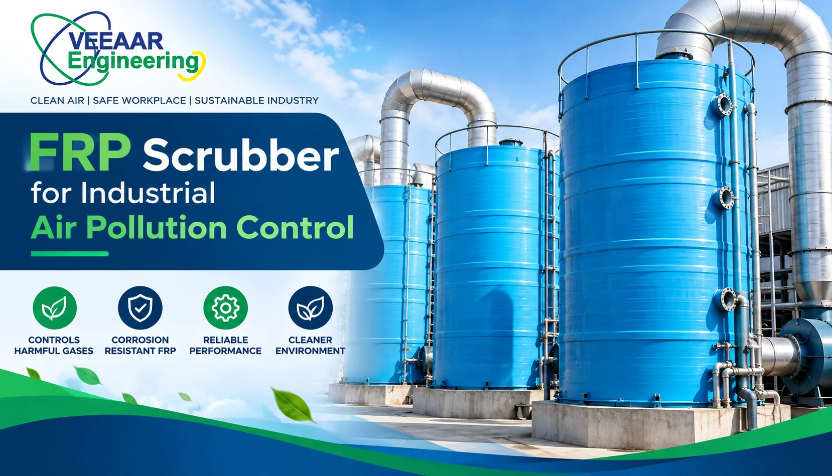
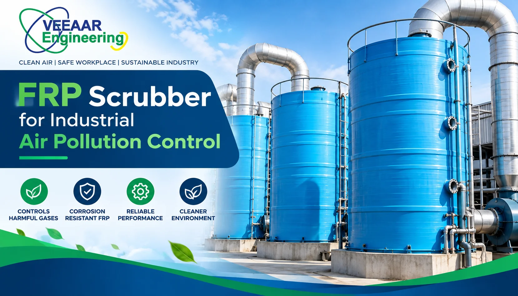
An FRP scrubber is a corrosion-resistant gas-cleaning system in which contaminated air contacts a liquid or reactive solution so selected pollutants can be captured or neutralised. FRP refers to fibre-reinforced plastic used for the shell, duct or internal components; it does not define the removal mechanism. Performance depends on pollutant chemistry, concentration, gas flow, temperature, moisture, reagent, contact design, pressure drop, mist separation and operating control.
Choose a scrubber only after characterising the actual exhaust stream and the required outlet condition. A system that works for an acid gas may not control a solvent vapour, oil mist or particulate plume. Source capture, duct design, fan selection, wastewater handling and safe chemical storage are part of the solution. The scrubber should be treated as a process system, not a stand-alone tank.
Vee Aar Engineering presents FRP tank and scrubber systems alongside industrial ventilation and air filtration and dust and fume filtration. A useful enquiry therefore starts with process and emission data, not only equipment diameter.
What FRP Means in a Scrubber
FRP is a composite of reinforcing fibres and a polymer resin. The combination can provide corrosion resistance and a favourable strength-to-weight ratio, but suitability depends on the exact resin, laminate construction, reinforcement, cure, thickness, temperature and chemical exposure. Saying that a scrubber is made of FRP is not enough to approve it.
The supplier should identify the resin system for the process side and structural laminate, corrosion allowance where used, liner arrangement, reinforcement type, fabrication method and design temperature. Chemical compatibility charts are useful screening tools, but actual concentration, contaminants, upset conditions and cleaning chemicals must be considered.
How a Wet FRP Scrubber Works
A fan moves contaminated gas from a hood or enclosure through ducting into the scrubber. Liquid is distributed through sprays or over packing, creating contact area between gas and liquid. Soluble gases transfer into the liquid; reactive chemicals may convert them into more stable forms. A mist eliminator captures entrained droplets before the treated gas reaches the outlet or stack.
The recirculation tank, pump, piping, strainers, nozzles and controls maintain liquid flow. Instruments may monitor pH, oxidation-reduction potential, conductivity, level, pressure drop, flow or reagent condition depending on the chemistry. Blowdown removes accumulated salts and contaminants; make-up water and reagent restore the operating solution.
Scrubber Types and Where They Fit
| Scrubber type | Primary mechanism | Typical selection reason |
|---|---|---|
| Packed-bed scrubber | Gas absorption across wetted packing | Soluble or reactive gases with high contact-area need |
| Spray tower | Droplets contact gas in an open chamber | Lower plugging risk and simpler internals |
| Venturi scrubber | High-energy atomisation and impaction | Fine particulate or combined gas/particle duty |
| Tray or plate scrubber | Gas bubbles through liquid stages | Defined staged contact and reaction |
| Two-stage system | Different media or chemistries in sequence | Multiple pollutants or incompatible treatment needs |
The names describe broad equipment families. Actual efficiency and pressure drop depend on dimensions, gas velocity, liquid-to-gas ratio, droplet or packing characteristics and pollutant properties. A packed tower with the wrong packing or poor liquid distribution can underperform even when the equipment label is correct.
Start with the Emission Source
Identify each process that releases fumes, gases, aerosols or particulates. Record normal production, start-up, cleaning, charging, maintenance and upset conditions. Batch processes may have short peaks that are hidden by an average concentration. Multiple sources connected to one header may operate simultaneously or intermittently.
Good source capture reduces the airflow that must be treated. Review hood position, enclosure, face velocity, cross-drafts, operator access and process containment. Increasing exhaust volume without improving capture can enlarge the fan, duct and scrubber while still allowing contaminants to escape into the workplace.
Pollutant and Gas-Stream Data to Collect
| Input | Why it matters | Evidence source |
|---|---|---|
| Pollutant identity | Determines absorption and reaction route | SDS, process chemistry and sampling |
| Concentration and peaks | Sets mass load and reagent demand | Testing and operating records |
| Gas flow | Sizes duct, fan and contact section | Capture design and traverse data |
| Temperature and humidity | Affect resin, evaporation and gas volume | Process measurements |
| Particles and droplets | Influence plugging and pre-treatment | Sampling and process review |
| Required outlet | Defines performance objective | Consent, permit or project criteria |
| Operating schedule | Sets turndown and control needs | Production plan |
Use measured data when available and document uncertainty. If a new line has no operating history, the process designer should provide a defensible mass balance and peak scenario. Never copy an airflow or concentration from a different plant without checking capture and production conditions.
Absorption and Chemical Reaction
Physical absorption transfers a pollutant into a liquid based on solubility and equilibrium. Chemical absorption reacts the pollutant in the liquid, maintaining a driving force for transfer. Reagent selection must consider reaction products, heat, salt formation, toxicity, pH range, corrosion and disposal.
More reagent is not automatically better. Excess concentration can increase cost, scaling, hazardous handling or secondary emissions. Control philosophy should define dosing setpoints, alarm limits, interlocks and response to probe failure. Laboratory or pilot testing may be appropriate for unusual mixtures.
Mass Transfer, Packing and Liquid Distribution
Packed beds use structured or random media to create a large wetted surface. The design balances contact area, gas velocity, liquid wetting, pressure drop and resistance to fouling. Packing material must tolerate the chemistry and temperature without distortion or degradation.
Uniform liquid distribution is essential. Dry zones reduce active area; excessive local flow can cause flooding. Nozzle layout, distributor level, recirculation rate and packing support should be inspectable. If solids or crystallising salts are expected, open packing, wash arrangements or a different scrubber type may be safer.
Mist Eliminator and Stack Carryover
Gas leaving the contact zone can carry droplets containing reagent and captured pollutant. A mist eliminator changes the droplet path so liquid collects and drains back. Its type, velocity, drainage and washability should match the droplet size and fouling risk.
Visible plume is not a complete performance test, and a clear outlet does not prove pollutant removal. Excessive carryover can corrode downstream equipment or create local deposition. Inspect differential pressure, wash condition, seals and drainage as part of routine maintenance.
Pressure Drop and Fan Selection
The fan must overcome losses from hoods, branches, dampers, ducts, scrubber internals, mist eliminator and stack at the required flow. Pressure drop changes with fouling, liquid rate and gas velocity. Select the fan at the system operating point with suitable margin, motor rating and corrosion protection.
Fan position affects leakage behaviour. An induced-draft arrangement can keep upstream contaminated equipment under negative pressure, but the fan may handle wet treated gas. A forced-draft arrangement changes leakage and material exposure. The designer should coordinate fan material, drainage, vibration, noise and maintenance access.
FRP Material Selection and Construction
Specify design temperature and pressure or vacuum, chemical concentration, resin, liner, structural laminate, thickness, supports, nozzles, flanges, manways and lifting points. Vacuum can be critical when dampers close or a fan operates against a blocked path. Large FRP vessels may need stiffening and careful support to control deformation.
Fabrication quality affects long-term performance. Request laminate procedures, cure control, visual and dimensional inspection, hardness or other specified tests, repair methods and traceability. Field joints and penetrations deserve the same attention as shop work.
Instrumentation and Controls
| Parameter | What it indicates | Typical action |
|---|---|---|
| Differential pressure | Airflow restriction or flooding trend | Inspect packing, mist eliminator and dampers |
| Liquid flow or pump status | Whether contact liquid is circulating | Alarm or stop source process as designed |
| pH or ORP | Reagent condition for selected chemistry | Dose, investigate probe or adjust blowdown |
| Tank level | Make-up, leakage or overflow risk | Control water and protect pump |
| Conductivity or density | Dissolved solids accumulation | Review blowdown |
| Gas flow | Capture and treatment volume | Correct fan or damper condition |
Instrumentation should be accessible for calibration and protected from fouling. A control loop is only useful when operators know what the reading means and what action to take. Define alarm priorities, fail-safe states and which process equipment must stop if scrubbing is unavailable.
Water, Reagent and Waste Management
Wet scrubbing transfers pollutants from gas into a liquid stream. The project must identify make-up water quality, reagent storage, bunding, dosing, spill control, blowdown treatment and authorised disposal. Do not describe a scrubber as eliminating pollution unless the resulting liquid and solids are managed responsibly.
Water balance should include evaporation, mist loss, reaction, overflow, drain and wash water. Recirculation reduces water use but can concentrate salts and contaminants. Define blowdown by chemistry and operating data rather than a fixed guess.
Safety and Hazard Review
Review chemical exposure, incompatible mixing, reaction heat, toxic release, confined spaces, fan isolation, electrical classification, static, pressure, access and manual handling. Provide eyewash, shower, ventilation, containment and personal protective equipment according to the site hazard assessment and applicable rules.
The scrubber should not create a dangerous reaction during an upset. Consider loss of water, wrong reagent, blocked nozzle, pump failure, high temperature, power failure and simultaneous contaminants. Interlocks must be based on the consequence of untreated exhaust, not convenience.
Installation and Commissioning Checklist
- Verify foundations, supports, nozzle orientation and access against approved drawings.
- Inspect FRP surfaces, joints, flanges and internals before closing the vessel.
- Confirm duct slope, drains, flexible connections, dampers and fan rotation.
- Flush piping and check pumps, spray coverage, leaks and tank operating level.
- Calibrate instruments and test alarms, dosing and process interlocks.
- Balance airflow at every capture point under representative operation.
- Establish clean-system pressure drop, liquid flow and chemistry baselines.
- Demonstrate performance using an agreed test method and operating condition.
Routine Maintenance That Protects Performance
Operators should trend pressure drop, recirculation flow, chemistry, make-up and blowdown. A stable number is not enough; readings should be compared with production load and the commissioning baseline. Sudden changes can indicate plugging, a leak, empty reagent, fan trouble or instrument failure.
Inspect pumps, strainers, nozzles, packing, supports, mist eliminator, tank, fan, duct and stack. Clean using methods compatible with the resin and deposits. Keep spare nozzles, gaskets, probes or pump components based on criticality and lead time. Document every chemical or process change that could affect scrubber duty.
Common Specification and Operating Mistakes
- Selecting from airflow alone without pollutant mass, chemistry or outlet target.
- Calling any FRP material chemically compatible without naming resin and temperature.
- Ignoring peak batch emissions and simultaneous source operation.
- Using excess capture air instead of improving hood design.
- Forgetting mist carryover, blowdown and reagent storage.
- Choosing packing that plugs in a solids-forming service.
- Installing instruments where they cannot be cleaned or calibrated.
- Accepting an efficiency percentage without inlet, outlet and test conditions.
How to Compare Two FRP Scrubber Proposals
Normalise both offers against the same gas flow, temperature, pollutant loading, required outlet and operating hours. Compare contact type, dimensions, material system, pressure drop, liquid rate, reagent, fan duty, instruments, mist eliminator, access, wastewater scope, documents and performance test.
List every exclusion. One quote may omit ducting, stack, fan, electrical panel, dosing skid, civil work, erection or testing. A lower equipment price can become a higher installed cost if interfaces are unclear. Technical deviations should be approved before commercial comparison.
Performance Testing and Acceptance
Define acceptance before purchase. The plan should identify the pollutant, sampling locations, method, production condition, inlet load, gas flow, reagent state, run duration and calculation basis. Testing during an unusually light production period may not represent the design duty, while testing during an uncontrolled upset may be unsafe and unrepeatable.
Confirm sampling ports, straight duct lengths, access platforms and utilities early. Poorly located ports can make representative measurements difficult. Calibrate instruments, record fan speed, pressure drop, liquid flow, pH or other chemistry indicators, and document which sources were operating during each run.
Acceptance should include more than an outlet concentration. Check capture at the source, visible leakage, fan operation, carryover, noise, vibration, wastewater generation, alarm response and operator understanding. Close punch-list items and establish a clean-system baseline before the final handover.
Troubleshooting by Symptom
| Observed symptom | Possible causes to investigate | First safe checks |
|---|---|---|
| High pressure drop | Fouled packing, flooded bed, closed damper | Trend liquid flow, inspect differential pressure and access safely |
| Low pressure drop | Low airflow, bypass, dry bed or instrument fault | Check fan, dampers, liquid distribution and gauge |
| Poor removal | Wrong chemistry, excess load, maldistribution or low contact | Verify inlet conditions, reagent and operating flows |
| Droplet carryover | Damaged mist eliminator, high velocity or poor drainage | Inspect wash, seals, orientation and drain path |
| Rapid reagent use | Higher load, dosing fault, leakage or wrong setpoint | Compare production, pH or ORP and tank balance |
Troubleshooting should protect workers from chemical and confined-space hazards. Do not open a scrubber or enter ductwork until the system is isolated, drained, ventilated and released under the site procedure. Process changes that repeatedly cause excursions may require redesign rather than more frequent cleaning.
Procurement Questions to Ask
- What inlet gas data and removal target form the design basis?
- Which scrubber mechanism and chemistry are proposed, and why?
- What resin, laminate, design temperature and corrosion basis apply?
- What gas and liquid pressure drops are expected clean and fouled?
- How are liquid distribution and mist elimination verified?
- Which instruments, alarms and interlocks are included?
- What water, reagent, blowdown and waste assumptions apply?
- Which installation, commissioning, performance-testing and training services are included?
Vee Aar Engineering Project Context
The live website describes Vee Aar Engineering as an air and water management solution provider established in 2013, with services spanning ventilation, filtration, smoke extraction and FRP systems. Review About Vee Aar Engineering and the company’s project and blog resources for context. Verify all project-specific materials, performance and commercial commitments in the final proposal.
Frequently Asked Questions
1. What is an FRP scrubber?
It is a gas-cleaning system that uses fibre-reinforced plastic for selected components and liquid contact to capture or react with suitable pollutants.
2. Why is FRP used for scrubbers?
A correctly selected FRP laminate can resist many corrosive environments while offering useful structural properties and lower weight than some alternatives.
3. Can one scrubber remove every pollutant?
No. Removal depends on pollutant chemistry, particle size, solubility, reagent, contact design and operating conditions.
4. What is the difference between a packed bed and spray tower?
A packed bed provides high wetted area through media; a spray tower uses droplets in a more open chamber and may tolerate fouling better.
5. Does an FRP scrubber remove particulate matter?
Some configurations can, but fine-particle capture may require a venturi or dedicated pre-control. The design must match the particle distribution.
6. How is scrubber efficiency verified?
Use an agreed test method at defined inlet load, flow and operating chemistry, with calibrated measurements and clear acceptance criteria.
7. What controls should a scrubber have?
Controls vary, but may include pressure drop, liquid flow, pump status, pH or ORP, level, dosing, conductivity, alarms and interlocks.
8. What happens to the captured pollution?
It enters the recirculating liquid or solids and must be handled through blowdown, treatment, recovery or authorised disposal.
9. How often should packing be cleaned?
There is no universal interval. Trend pressure drop, liquid distribution and process loading, then inspect and clean under a documented plan.
10. Can an FRP scrubber handle hot gas?
Only within the verified temperature limits of the resin, laminate, internals and process design. Cooling or dilution may be required.
11. What information is needed for a quote?
Provide pollutant identity and load, airflow, temperature, humidity, particles, operating schedule, outlet requirement, utilities, layout and site constraints.
12. Is the fan included with the scrubber?
Scope varies. The quotation should state fan, motor, duct, stack, panel, pumps, dosing, installation and testing explicitly.
Turn the Scrubber into a Reliable Emission Control System
A dependable FRP scrubber begins with accurate source data and ends with measurable operation, maintainable internals and responsible liquid-waste handling. Share the process, pollutant data, airflow, temperature, required outlet, operating hours, utilities and layout with Vee Aar Engineering. Review the FRP tank and scrubber service and use the Veeaar Engineering contact pageto request a complete design-basis proposal rather than an equipment-only estimate.